The plates were joined together using angles an d rivets to obtain plate girders of desired size. Except where the ends of stiffeners are welded to the flange fillet welds joining transverse stiffeners to girder webs shall start or termi-.

Masterseries How To Design Web To Flange Welds In Plate Girders
Knife plate connection design timber.

. The vertical reactions both gravity and uplift and the horizontal chord force are transferred to the column through the weld between the Joist Girder top chord and the knife plate and then through the. Times the nominal weld size. JUNE 2008 LRFD BRIDGE DESIGN 6-1 6.
Basler New Provisions for Plate Girder Design. The moment-resisting capacities of plate girders lie somewhere between those of deep standard rolled wide-flange shapes and those of trusses. They offer the following advantages over the standard rolled sections 1.
Design of Plate Girders 91 INTRODUCTION The most common type of plate girder is an I-shaped section built up from two flange plates and one web plate as shown in Figs. But the results are most favorable and encouraging. Steel girders shall be rolled -beams I welded plate I-girders or tubbox girders.
STEEL STRUCTURES 61 Materials Structural steel in the form of rolled steel beams or welded plate girders is used for bridge superstructures. Ing capao1ty of th1nwebplate g1dersThe work oonsisted of analytioal stUdies and a series of tests on full size welded steel girders. General design provisions are also addressed in this module including flexural resistance provided by a bolted field splice at the Strength and Service limit states as well as detailing considerations.
Plate Girder Design Using LRFD CYNTHIA J. Design the welds between the flange and web of a plate girder. Pyw Design strength of web fyw γm γm Material safety factor for steel 115 The elastic critical stress Refer Table 1 of the previous chapter has been simplified and given based on ad and td as given in Table - 1.
The following note discusses the standard formula for the shear flow between web and flanges of a doubly symmetric beam which is used for weld design and gives the background to the formula in Eurocode 3 Part 51. Some or the findings of this researob a. However it is a necessary and important part of plate girder design when applying the Load and Resistance Factor Design LRFD Specification1 A beam can be a rolled or a welded shape but it does not have.
Joist tie-plate connection design. The span is 36 m and carries two concentrated loads as shown in Fig. The economics of design expected length and location of a bridge generally govern the choice of girder material.
On the compression flange the girder is called compacted section otherwise it will be called as non-compacted section. 1The web plates of plate girders resist the shear force and the shear stress is uniformly distributed over entire cross sectional area of the web. Summarized here and the more important design.
Curvature and girder properties. 2 Determine yield mode capacity at each bolt shear plane. Up to 5 cash back Welded Plate Girder 71 Introduction.
The flanges of plate girders resist the bending moment. Enough data to draw precise design reconnnendations for bridge girders. ASSUMPTIONS FOR THE DESIGN OF PLATE GIRDER BRIDGES Following assumptions are made in the design of plate girder bridges.
Examples of crane girder design to the Eurocodes. In this situation girders are to be fabricated using flange and web plates as per requirement. As an example of the formulation of a practical design problem and the optimization solution process we will present the design of a welded plate girder for a highway bridge to minimize its cost Arora et al 1997.
For these beams ready-made I sections are not suitable since their depth is limited due to buckling of the web. Design a plate girder. The girder showed in Fig.
Plate girder bridges Riveted and welded Introduction Plate girders became popular in the late 1800s when t hey were used in construction of railroad bridges. ZAHN What differentiates a beam from a plate girder. Examples of flexible con-nections include framing angles top angles of seated beam connections and simple end plate connections.
14 RELEVANCY OF THE PROJECT This study is relevant to clearly see the different between the Indian Standard. The use of welded plate girders for short to medium span highway bridges offers greatest flexibility in choosing the most economical section. Design example includes detailed design computations for the following bridge features.
As a re8t design recommendations were prepared whioh are incorporated in the new AlSO TDs1gn Speoifioations. The design of a plate girder element is the. Work out Examples Design a Welded plate girder with a simply support span of 56 ft to support a.
Welded plate girders are used in many practical applications such as overhead cranes and highway and railway bridges. In rare instances integral pier caps or substructures will be designed using. This may seem to be a trivial question.
Illustrated through the design example presented herein. PLATE GIRDER Worked Example - 1 Made by SSSR Date 15-04-00 Structural Steel Design Project Calculation Sheet Checked by PU Date 25-04-00 PROBLEM. 631 Steel Components All structural steel components including structural steel.
Specifically the example illustrates the design. By the end of this study the author will come out with the design example and the spreadsheet to ease the calculation of designing welded plate girder bridges for all codes being studied. An example is also presented.
Beams of long span subjected to heavy loads are encountered in buildings and bridges. David Brown of the SCI rises to the challenge The problem According to the contribution in Verulam a number of problems exist with the design of a mono-symmetric member a plate welded to the top flange of. Design of simple beams Built-up beams Plate girders and g antry girders.
Depending on the type of girder use Chapter B F and Chapter G accordingly. Keywords Bolted Field Splices Welded Splices Steel Girders Bolts Splice Plates Steel Bridges 10. The example illustrates the design of a typical three-span continuous straight steel I-girder bridge with spans of 140-0 175-0 140-0.
With the guidance of the results described above further research is continuing on the fatigue of welded plate girders. The current AWS design specifications l for welded bridges are based on a con sideration of fatigue. Welded plate girders can be designed as long and as deep as required by the design and fabrication method.
Conc rete deck steel plate girder bolted field splice shear connectors bearing stiffeners welded connections elastomeric bearing cantilever abutment and. PLATE GIRDERS II where qe Elastic critical shear strength values to be used in design for different values of ad and dt are tabulated in Table - 1. At the same time this increase in the plication of welding to bridges has resulted in a greater need for information concerning the fatigue behavior of such structures.
Way bridges particularly for welded girder bridges. E1 is fully restrained against lateral buckling throughout its span.
2

Pdf Optimum Design Of Plate Girder
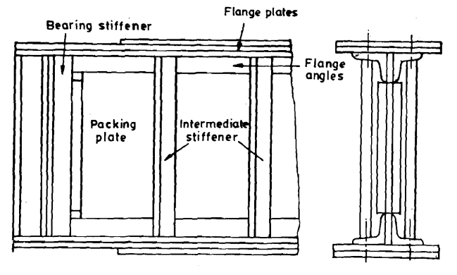
Plate Girder Structural Guide

Pdf Design Of Plate Girders Mik Wanul Khosiin Academia Edu
2
Masterseries How To Design Web To Flange Welds In Plate Girders
2

Pin On Tree Wall Murals
0 comments
Post a Comment